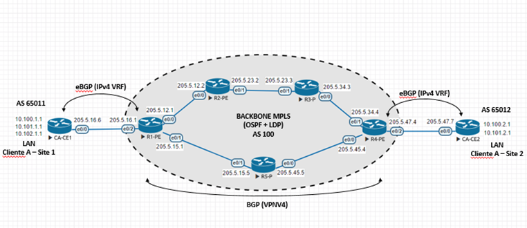
(Acredite, é um resumo extremamente simplificado)
MPLS L3VPN é para mim o tópico mais complicado do CCIE R&S. E olha que o conteúdo nem é tão aprofundado, já que MPLS é mais detalhada no CCIE SP.
Mesmo assim, para a MPLS L3VPN funcionar precisamos “juntar” várias partes que individualmente já são complicadas (IGP, LDP, VRF, BGP,…).
MPLS – Multi Protocol Label Switching, é um protocolo de tunelamento, multi-protocolo (suporta IP, IPv6, PPP,…) que permite o encaminhamento de pacotes com base em label layer 2.
MPLS L3VPN é a junção da MPLS com o BGP, onde passamos a ter roteamento entre o roteador da “operadora” e do “cliente” (daí a parte L3 do nome) e a separação do tráfego do cliente em VRF (e por isso chamado de VPN).
VRF – Virtual Routing and Forwarding, é uma forma de virtualização do roteador. Com VRFs passamos a ter tabelas de roteamento separadas, e por isso o tráfego de clientes diferentes não se misturam (e podem até ter o mesmo endereçamento).
Em uma MPLS L3VPN temos os roteadores CE falando com os roteadores PE, que então traduzem as rotas para rotas VPNv4 e enviam para os outros PE via MP-BGP. E o tráfego entre os PE (no backbone) é encaminhado com base no labels MPLS.

1) Configuração inicial dos roteadores do Backbone.
Vamos começar configurado os IPs e hostnames dos roteadores que serão nosso backbone MPLS. Este passo não é específico da configuração de MPLS L3VPN.
Configuração em cada roteador do backbone:
hostname R1-PE
interface Loopback0
ip address 200.10.1.1 255.255.255.255
interface Ethernet0/0
ip address 205.5.12.1 255.255.255.0
interface Ethernet0/1
ip address 205.5.15.1 255.255.255.0

hostname R2-PE
interface Loopback0
ip address 200.10.2.2 255.255.255.255
interface Ethernet0/0
ip address 205.5.12.2 255.255.255.0
interface Ethernet0/1
ip address 205.5.23.2 255.255.255.0

hostname R3-P
interface Loopback0
ip address 200.10.3.3 255.255.255.255
interface Ethernet0/0
ip address 205.5.34.3 255.255.255.0
interface Ethernet0/1
ip address 205.5.23.3 255.255.255.0

hostname R4-PE
interface Loopback0
ip address 200.10.4.4 255.255.255.255
interface Ethernet0/0
ip address 205.5.45.4 255.255.255.0
interface Ethernet0/1
ip address 205.5.34.4 255.255.255.0

hostname R5-P
interface Loopback0
ip address 200.10.5.5 255.255.255.255
interface Ethernet0/0
ip address 205.5.45.5 255.255.255.0
interface Ethernet0/1
ip address 205.5.15.5 255.255.255.0
2) Configurando MPLS (OSPF + LDP) no Backbone.
Para termos uma rede MPLS funcional, precisamos que os roteadores do backbone sejam capazes de fazer o roteamento entre eles.
Neste exemplo vamos usar OSPF, habilitando o roteamento em todas as interfaces (ethernets e loopbacks) na área 0.
O backbone é composto por roteadores P e PE, sendo que P (Provider Router) são os roteadores responsáveis por fazerem o encaminhamento com base nos labels MPLS. Provider Edge (PE) é o roteador do backbone mais próximo do cliente, tem MPLS habilitada, VRFs, e é responsável pela MP-BGP (VPN).
Junto com o OSPF vamos configurar o LDP – Label Distribution Protocol, que será o responsável por gerar e distribuir labels entre os roteadores. Cada roteador gera labels para seus prefixos e então faz o anuncio para seus vizinhos (os labels tem significado local apenas).
Felizmente, quando usamos OSPF e LDP podemos automatizar o processo, de maneira que cada rota/interface conhecida pelo roteador (prefixos que estão na RIB) receba um label.
Configuração em todos os roteadores do backbone:
router ospf 1
mpls ldp autoconfig
network 200.10.0.0 0.0.255.255 area 0
network 205.5.0.0 0.0.255.255 area 0
Podemos verificar a configuração com os comandos normais de OSPF e também com comandos específicos de MPLS.
R1#show ip ospf neighbor
Neighbor ID     Pri   State           Dead Time   Address         Interface
200.10.5.5        1   FULL/DR         00:00:31    205.5.15.5      Ethernet0/1
200.10.2.2        1   FULL/DR         00:00:39    205.5.12.2      Ethernet0/0

R1-PE#show ip route ospf
Codes: L - local, C - connected, S - static, R - RIP, M - mobile, B - BGP
       D - EIGRP, EX - EIGRP external, O - OSPF, IA - OSPF inter area
       N1 - OSPF NSSA external type 1, N2 - OSPF NSSA external type 2
       E1 - OSPF external type 1, E2 - OSPF external type 2
       i - IS-IS, su - IS-IS summary, L1 - IS-IS level-1, L2 - IS-IS level-2
       ia - IS-IS inter area, * - candidate default, U - per-user static route
       o - ODR, P - periodic downloaded static route, H - NHRP, l - LISP
       a - application route
       + - replicated route, % - next hop override
Gateway of last resort is not set

      200.10.2.0/32 is subnetted, 1 subnets
O        200.10.2.2 [110/11] via 205.5.12.2, 01:47:27, Ethernet0/0
      200.10.3.0/32 is subnetted, 1 subnets
O        200.10.3.3 [110/21] via 205.5.12.2, 01:47:27, Ethernet0/0
      200.10.4.0/32 is subnetted, 1 subnets
O        200.10.4.4 [110/21] via 205.5.15.5, 01:47:27, Ethernet0/1
      200.10.5.0/32 is subnetted, 1 subnets
O        200.10.5.5 [110/11] via 205.5.15.5, 01:47:27, Ethernet0/1
O     205.5.23.0/24 [110/20] via 205.5.12.2, 01:47:27, Ethernet0/0
O     205.5.34.0/24 [110/30] via 205.5.15.5, 01:47:27, Ethernet0/1
                    [110/30] via 205.5.12.2, 01:47:27, Ethernet0/0
O     205.5.45.0/24 [110/20] via 205.5.15.5, 01:47:27, Ethernet0/1
R1-PE#
O LDP forma vizinhança, semelhante à protocolos de roteamento.
R1-PE#show mpls ldp neighbor
    Peer LDP Ident: 200.10.2.2:0; Local LDP Ident 200.10.1.1:0
        TCP connection: 200.10.2.2.42678 - 200.10.1.1.646
        State: Oper; Msgs sent/rcvd: 203/203; Downstream
        Up time: 02:41:04
        LDP discovery sources:
          Ethernet0/0, Src IP addr: 205.5.12.2
        Addresses bound to peer LDP Ident:
          205.5.12.2      205.5.23.2      200.10.2.2
    Peer LDP Ident: 200.10.5.5:0; Local LDP Ident 200.10.1.1:0
        TCP connection: 200.10.5.5.49563 - 200.10.1.1.646
        State: Oper; Msgs sent/rcvd: 198/197; Downstream
        Up time: 02:34:48
        LDP discovery sources:
          Ethernet0/1, Src IP addr: 205.5.15.5
        Addresses bound to peer LDP Ident:
          205.5.45.5      200.10.5.5      205.5.15.5
R1-PE#
Verifique também se o roteador está alocando labels para os prefixos conhecidos.
R1-PE#show mpls forwarding-table
Local      Outgoing   Prefix           Bytes Label   Outgoing   Next Hop
Label      Label      or Tunnel Id     Switched      interface
16         Pop Label  200.10.2.2/32    0             Et0/0      205.5.12.2
17         17         200.10.3.3/32    0             Et0/0      205.5.12.2
18         19         200.10.4.4/32    0             Et0/1      205.5.15.5
19         Pop Label  200.10.5.5/32    0             Et0/1      205.5.15.5
20         Pop Label  205.5.23.0/24    0             Et0/0      205.5.12.2
22         22         205.5.34.0/24    0             Et0/0      205.5.12.2
           24         205.5.34.0/24    0             Et0/1      205.5.15.5
23         Pop Label  205.5.45.0/24    0             Et0/1      205.5.15.5

R1-PE#show ip cef 200.10.4.4
200.10.4.4/32
  nexthop 205.5.15.5 Ethernet0/1 label 19
R1-PE#
Por fim, podemos verificar o encaminhamento do tráfego com o tracert.
R1-PE#traceroute 200.10.4.4
Type escape sequence to abort.
Tracing the route to 200.10.4.4
VRF info: (vrf in name/id, vrf out name/id)
  1 205.5.15.5 [MPLS: Label 19 Exp 0] 1 msec 1 msec 1 msec
  2 205.5.45.4 2 msec 3 msec *
R1-PE#
Esta é a configuração mínima para MPLS funcionar.
3) Configurando VRF e os CEs.
Temos nosso backbone funcionando (MPLS – OSPF + LDP), e agora vamos configurar uma VRF para o cliente nos roteadores PE (R1 e R4).
Também vamos fazer a configuração inicial dos roteadores CE.
CE – Customer Edge, é o roteador “do cliente”. Obrigatoriamente tem uma conexão com o PE, e não tem MPLS configurada, nem VRF.
R1-PE:
vrf definition CLIENTE-A
rd 100:1
address-family ipv4
route-target both 100:1
!
interface Ethernet0/2
vrf forwarding CLIENTE-A
ip address 205.5.16.1 255.255.255.0

CA-CE1:
interface Loopback0
ip address 201.10.1.1 255.255.255.255
interface Loopback100
ip address 10.100.1.1 255.255.255.0
interface Loopback101
ip address 10.101.1.1 255.255.255.0
interface Loopback102
ip address 10.102.1.1 255.255.255.0
interface Ethernet0/0
ip address 205.5.16.6 255.255.255.0

R4-PE:
vrf definition CLIENTE-A
rd 100:1
address-family ipv4
route-target both 100:1
!
interface Ethernet0/2
vrf forwarding CLIENTE-A
ip address 205.5.47.4 255.255.255.0

CA-CE2:
interface Loopback0
ip address 201.10.2.2 255.255.255.255
interface Loopback100
ip address 10.100.2.1 255.255.255.0
interface Loopback101
ip address 10.101.2.1 255.255.255.0
interface Ethernet0/0
ip address 205.5.47.7 255.255.255.0
Observer que nos PEs temos a VRF e nela temos dois componentes importantes:
-
RD (Route Distinguisher): Tag usada para “distinguir” rotas. Com o RD uma rota associada a VRF A passa a ser diferente de uma rota aprendida na VRF B, ainda que o prefixo e a máscara sejam os mesmos.
-
RT (Route Target): Apesar do formato semelhante, tem função diferente do RD. O Route Target nos permite selecionar o que queremos importar da/para VRF.
4) Roteamento entre CE e PE (BGP).
Nosso próximo passo é a configuração do roteamento entre os roteadores CE e os roteadores PEs.
Neste exemplo vamos usar eBGP entre os sites e o backbone, mas também é possível usar outros protocolos (RIP, EIGRP, OSPF) para esta função.
Observe que do lado do cliente a configuração do BGP é normal.
CA-CE1:
router bgp 65011
redistribute connected
neighbor 205.5.16.1 remote-as 100

CA-CE2:
router bgp 65012
redistribute connected
neighbor 205.5.47.4 remote-as 100
Do lado da operadora a única diferença é que o BGP é configurado com a utilização da VRF previamente configurada (CLIENTE-A).
R1-PE:
router bgp 100
no bgp default ipv4-unicast
address-family ipv4 vrf CLIENTE-A
  neighbor 205.5.16.6 remote-as 65011
  neighbor 205.5.16.6 activate

R4-PE:
router bgp 100
no bgp default ipv4-unicast
address-family ipv4 vrf CLIENTE-A
  neighbor 205.5.47.7 remote-as 65012
  neighbor 205.5.47.7 activate
Com isso os PEs já são capazes de aprender as rotas dos CEs. Para verificar basta usar o comando show bgp vpnv4 unicast all [summary].
R1-PE#show bgp vpnv4 unicast all summary
BGP router identifier 200.10.1.1, local AS number 100
BGP table version is 19, main routing table version 19
9 network entries using 1368 bytes of memory
9 path entries using 720 bytes of memory
3/2 BGP path/bestpath attribute entries using 456 bytes of memory
2 BGP AS-PATH entries using 48 bytes of memory
1 BGP extended community entries using 24 bytes of memory
0 BGP route-map cache entries using 0 bytes of memory
0 BGP filter-list cache entries using 0 bytes of memory
BGP using 2616 total bytes of memory
BGP activity 9/0 prefixes, 9/0 paths, scan interval 60 secs

Neighbor        V           AS MsgRcvd MsgSent   TblVer  InQ OutQ Up/Down  State/PfxRcd
205.5.16.6      4        65011     143     141       19    0    0 02:01:59        5
R1-PE#

R1-PE#show bgp vpnv4 unicast all
BGP table version is 6, local router ID is 200.10.1.1
Status codes: s suppressed, d damped, h history, * valid, > best, i - internal,
              r RIB-failure, S Stale, m multipath, b backup-path, f RT-Filter,
              x best-external, a additional-path, c RIB-compressed,
Origin codes: i - IGP, e - EGP, ? - incomplete
RPKI validation codes: V valid, I invalid, N Not found

     Network          Next Hop            Metric LocPrf Weight Path
Route Distinguisher: 100:1 (default for vrf CLIENTE-A)
*>  10.100.1.0/24    205.5.16.6               0             0 65011 ?
*>  10.101.1.0/24    205.5.16.6               0             0 65011 ?
*>  10.102.1.0/24    205.5.16.6               0             0 65011 ?
*>  201.10.1.1/32    205.5.16.6               0             0 65011 ?
r>  205.5.16.0       205.5.16.6               0             0 65011 ?
R1-PE#

R4-PE#show bgp vpnv4 unicast all
BGP table version is 5, local router ID is 200.10.4.4
Status codes: s suppressed, d damped, h history, * valid, > best, i - internal,
              r RIB-failure, S Stale, m multipath, b backup-path, f RT-Filter,
              x best-external, a additional-path, c RIB-compressed,
Origin codes: i - IGP, e - EGP, ? - incomplete
RPKI validation codes: V valid, I invalid, N Not found

     Network          Next Hop            Metric LocPrf Weight Path
Route Distinguisher: 100:1 (default for vrf CLIENTE-A)
*>  10.100.2.0/24    205.5.47.7               0             0 65012 ?
*>  10.101.2.0/24    205.5.47.7               0             0 65012 ?
*>  201.10.2.2/32    205.5.47.7               0             0 65012 ?
r>  205.5.47.0       205.5.47.7               0             0 65012 ?
R4-PE#
5) Agora a VPNv4 (BGP).
No momento temos os dois sites falando com o backbone, mas eles ainda não falam entre si.
Para isso precisamos configurar o MP-BGP no PE router para importar as rotas da VRF e divulgar via iBGP para o outro PE.
R1-PE:
router bgp 100
neighbor 200.10.4.4 remote-as 100
neighbor 200.10.4.4 update-source Loopback0
!
address-family vpnv4
  neighbor 200.10.4.4 activate
  neighbor 200.10.4.4 send-community extended

R4-PE:
router bgp 100
neighbor 200.10.1.1 remote-as 100
neighbor 200.10.1.1 update-source Loopback0
!
address-family vpnv4
  neighbor 200.10.1.1 activate
  neighbor 200.10.1.1 send-community extended
Vamos à verificação.
R1-PE#show bgp vpnv4 unicast all summary
BGP router identifier 200.10.1.1, local AS number 100
BGP table version is 19, main routing table version 19
9 network entries using 1368 bytes of memory
9 path entries using 720 bytes of memory
3/2 BGP path/bestpath attribute entries using 456 bytes of memory
2 BGP AS-PATH entries using 48 bytes of memory
1 BGP extended community entries using 24 bytes of memory
0 BGP route-map cache entries using 0 bytes of memory
0 BGP filter-list cache entries using 0 bytes of memory
BGP using 2616 total bytes of memory
BGP activity 9/0 prefixes, 9/0 paths, scan interval 60 secs

Neighbor        V           AS MsgRcvd MsgSent   TblVer  InQ OutQ Up/Down  State/PfxRcd
200.10.4.4      4          100      20      20       19    0    0 00:10:32        4
205.5.16.6      4        65011      29      27       19    0    0 00:19:56        5
R1-PE#

R1-PE#show bgp vpnv4 unicast all
BGP table version is 19, local router ID is 200.10.1.1
Status codes: s suppressed, d damped, h history, * valid, > best, i - internal,
              r RIB-failure, S Stale, m multipath, b backup-path, f RT-Filter,
              x best-external, a additional-path, c RIB-compressed,
Origin codes: i - IGP, e - EGP, ? - incomplete
RPKI validation codes: V valid, I invalid, N Not found

     Network          Next Hop            Metric LocPrf Weight Path
Route Distinguisher: 100:1 (default for vrf CLIENTE-A)
*>  10.100.1.0/24    205.5.16.6               0             0 65011 ?
*>i 10.100.2.0/24    200.10.4.4               0    100      0 65012 ?
*>  10.101.1.0/24    205.5.16.6               0             0 65011 ?
*>i 10.101.2.0/24    200.10.4.4               0    100      0 65012 ?
*>  10.102.1.0/24    205.5.16.6               0             0 65011 ?
*>  201.10.1.1/32    205.5.16.6               0             0 65011 ?
*>i 201.10.2.2/32    200.10.4.4               0    100      0 65012 ?
r>  205.5.16.0       205.5.16.6               0             0 65011 ?
*>i 205.5.47.0       200.10.4.4               0    100      0 65012 ?
R1-PE#
Verficação no CE.
CA-CE1#show ip route bgp
Codes: L - local, C - connected, S - static, R - RIP, M - mobile, B - BGP
       D - EIGRP, EX - EIGRP external, O - OSPF, IA - OSPF inter area
       N1 - OSPF NSSA external type 1, N2 - OSPF NSSA external type 2
       E1 - OSPF external type 1, E2 - OSPF external type 2
       i - IS-IS, su - IS-IS summary, L1 - IS-IS level-1, L2 - IS-IS level-2
       ia - IS-IS inter area, * - candidate default, U - per-user static route
       o - ODR, P - periodic downloaded static route, H - NHRP, l - LISP
       a - application route
       + - replicated route, % - next hop override
Gateway of last resort is not set

      10.0.0.0/8 is variably subnetted, 8 subnets, 2 masks
B        10.100.2.0/24 [20/0] via 205.5.16.1, 02:11:27
B        10.101.2.0/24 [20/0] via 205.5.16.1, 02:11:27
      201.10.2.0/32 is subnetted, 1 subnets
B        201.10.2.2 [20/0] via 205.5.16.1, 02:11:27
B     205.5.47.0/24 [20/0] via 205.5.16.1, 02:11:27
CA-CE1#
Para finalizar, podemos testar a comunicação entre os sites usando o comando traceroute.
CA-CE1#traceroute 10.100.2.1
Type escape sequence to abort.
Tracing the route to 10.100.2.1
VRF info: (vrf in name/id, vrf out name/id)
  1 205.5.16.1 1 msec 1 msec 1 msec
  2 205.5.15.5 [MPLS: Labels 19/22 Exp 0] 4 msec 3 msec 3 msec
  3 205.5.47.4 [AS 65012] [MPLS: Label 22 Exp 0] 2 msec 1 msec 1 msec
  4 205.5.47.7 [AS 65012] 2 msec 4 msec *
CA-CE1#
Adicionando o segundo cliente
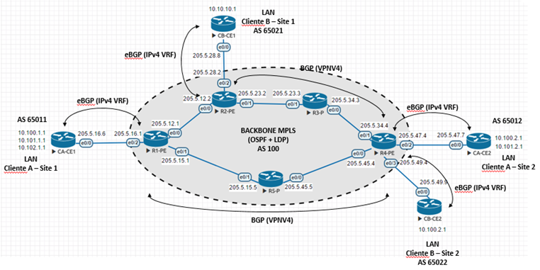
Para incrementar um pouco nosso cenário, e demonstrar o benefício da solução (VRF/BGP/MPLS), vamos adicionar um segundo cliente com mais dois sites.

CB-CE1:
interface Loopback100
 ip address 10.10.10.1 255.255.255.0
interface Ethernet0/0
 ip address 205.5.28.8 255.255.255.0
!
router bgp 65021
 redistribute connected
 neighbor 205.5.28.2 remote-as 100

R2-PE:
vrf definition CLIENTE-B
 rd 100:2
 !
 address-family ipv4
  route-target export 100:2
  route-target import 100:2
!
interface Ethernet0/2
 vrf forwarding CLIENTE-B
 ip address 205.5.28.2 255.255.255.0
!
router bgp 100
 no bgp default ipv4-unicast
 neighbor 200.10.4.4 remote-as 100
 neighbor 200.10.4.4 update-source Loopback0
 !
 address-family vpnv4
  neighbor 200.10.4.4 activate
  neighbor 200.10.4.4 send-community extended
 !
 address-family ipv4 vrf CLIENTE-B
  neighbor 205.5.28.8 remote-as 65021
  neighbor 205.5.28.8 activate

CB-CE2
interface Loopback100
 ip address 10.100.2.1 255.255.255.0
interface Ethernet0/0
 ip address 205.5.49.9 255.255.255.0
!
router bgp 65022
 redistribute connected
 neighbor 205.5.49.4 remote-as 100

R4-PE
vrf definition CLIENTE-B
 rd 100:2
 !
 address-family ipv4
  route-target export 100:2
  route-target import 100:2
!
interface Ethernet0/3
 vrf forwarding CLIENTE-B
 ip address 205.5.49.4 255.255.255.0
!
router bgp 100
 no bgp default ipv4-unicast
 neighbor 200.10.2.2 remote-as 100
 neighbor 200.10.2.2 update-source Loopback0
 !
 address-family vpnv4
  neighbor 200.10.2.2 activate
  neighbor 200.10.2.2 send-community extended
 !
 address-family ipv4 vrf CLIENTE-B
  neighbor 205.5.49.9 remote-as 65022
  neighbor 205.5.49.9 activate
 exit-address-family
Podemos ver que CB-CE2 aprendeu as rotas do CB-CE1, via MPLS L3VPN.
CB-CE2#show ip bgp
BGP table version is 5, local router ID is 10.100.2.1
Status codes: s suppressed, d damped, h history, * valid, > best, i - internal,
              r RIB-failure, S Stale, m multipath, b backup-path, f RT-Filter,
              x best-external, a additional-path, c RIB-compressed,
Origin codes: i - IGP, e - EGP, ? - incomplete
RPKI validation codes: V valid, I invalid, N Not found

     Network          Next Hop            Metric LocPrf Weight Path
 *>  10.10.10.0/24    205.5.49.4                             0 100 65021 ?
 *>  10.100.2.0/24    0.0.0.0                  0         32768 ?
 *>  205.5.28.0       205.5.49.4                             0 100 65021 ?
 *>  205.5.49.0       0.0.0.0                  0         32768 ?
CB-CE2#

CB-CE2#show ip route bgp
Codes: L - local, C - connected, S - static, R - RIP, M - mobile, B - BGP
       D - EIGRP, EX - EIGRP external, O - OSPF, IA - OSPF inter area
       N1 - OSPF NSSA external type 1, N2 - OSPF NSSA external type 2
       E1 - OSPF external type 1, E2 - OSPF external type 2
       i - IS-IS, su - IS-IS summary, L1 - IS-IS level-1, L2 - IS-IS level-2
       ia - IS-IS inter area, * - candidate default, U - per-user static route
       o - ODR, P - periodic downloaded static route, H - NHRP, l - LISP
       a - application route
       + - replicated route, % - next hop override
Gateway of last resort is not set

      10.0.0.0/8 is variably subnetted, 3 subnets, 2 masks
B        10.10.10.0/24 [20/0] via 205.5.49.4, 00:01:03
B     205.5.28.0/24 [20/0] via 205.5.49.4, 00:01:03
CB-CE2#

CB-CE2#traceroute 10.10.10.1
Type escape sequence to abort.
Tracing the route to 10.10.10.1
VRF info: (vrf in name/id, vrf out name/id)
  1 205.5.49.4 0 msec 1 msec 1 msec
  2 205.5.34.3 [MPLS: Labels 18/23 Exp 0] 4 msec 1 msec 1 msec
  3 205.5.28.2 [AS 65021] [MPLS: Label 23 Exp 0] 1 msec 2 msec 1 msec
  4 205.5.28.8 [AS 65021] 1 msec 2 msec *
CB-CE2#
E para fechar, podemos ver no R4-PE que as rotas estão separadas por VRFs.
R4-PE#show bgp vpnv4 unicast all
BGP table version is 21, local router ID is 200.10.4.4
Status codes: s suppressed, d damped, h history, * valid, > best, i - internal,
              r RIB-failure, S Stale, m multipath, b backup-path, f RT-Filter,
              x best-external, a additional-path, c RIB-compressed,
Origin codes: i - IGP, e - EGP, ? - incomplete
RPKI validation codes: V valid, I invalid, N Not found

     Network          Next Hop            Metric LocPrf Weight Path
Route Distinguisher: 100:1 (default for vrf CLIENTE-A)
 *>i 10.100.1.0/24    200.10.1.1               0    100      0 65011 ?
 *>  10.100.2.0/24    205.5.47.7               0             0 65012 ?
 *>i 10.101.1.0/24    200.10.1.1               0    100      0 65011 ?
 *>  10.101.2.0/24    205.5.47.7               0             0 65012 ?
 *>i 10.102.1.0/24    200.10.1.1               0    100      0 65011 ?
 *>i 201.10.1.1/32    200.10.1.1               0    100      0 65011 ?
 *>  201.10.2.2/32    205.5.47.7               0             0 65012 ?
 *>i 205.5.16.0       200.10.1.1               0    100      0 65011 ?
 r>  205.5.47.0       205.5.47.7               0             0 65012 ?
Route Distinguisher: 100:2 (default for vrf CLIENTE-B)
 *>i 10.10.10.0/24    200.10.2.2               0    100      0 65021 ?
 *>  10.100.2.0/24    205.5.49.9               0             0 65022 ?
 *>i 205.5.28.0       200.10.2.2               0    100      0 65021 ?
 r>  205.5.49.0       205.5.49.9               0             0 65022 ?
R4-PE#
Observe que o cliente B, no site 2, tem o endereço 10.100.2.0/24, que já estava em uso no site site 2 do cliente A. Mas graças a virtualização da tabela de roteamento (VRF) não temos problema.
Mais informações:
Até a próxima.


34 Comments
Bom dia, Andre fiz a configuracao conforme o tutorial do CLIENTE-A primeiro, o cenario se comportou conforme os passos, ospf formou vizinhanca, ebgp tambem, montei as vrf, ibgp tambem startou normalmente, realizei as Verficação no CE e no PE, ca-ce1 recebe as rotas do ca-ce2, mas ao fazer o teste de comunicacao entre eles, nao ha comunicação, se precisar de mais informações por favor estou a disposicao, o que poderia estar ocorrendo estou usando as ios L3-ADVENTERPRISEK9-M-15.4-2T em todo os hosts.
Olá Gianor,
faz tempo que não mexe com isso… No CE2 tem as rotas do CE1?
Se tiver pode ser bug mesmo…
Andre, boa noite fiz mais uns testes aqui e descobri o erro nas loopbacks 0, ao invés de setar o /32 coloquei elas como /24.
consegui ver esse erro apos ver um modulo do curso ead da #datacom palestra da Tatiane Figueiredo da datacom..
Ótimo.
Gostaria de recomendar o curso de MPLS abaixo:
https://www.youtube.com/user/miovieira/videos
Bacana!!
olá André, se os Clientes quisessem acrescentar mas um site cada, como ficaria a configuração? estive acrescentando mas um site para o Cliente A e B e não existe comunicação entre os novos sites e os antigos, o que deve estar faltando?
Olá, para o mesmo cliente bastaria divulgar as rotas dos novos sites, usando a mesma VRF. Verifique o OSPF e o BGP/VRF.
Se for ter “outro cliente”, teria que preparar o backbone com uma nova VRF.
Saudações André!
Desde já agradeço por seu trabalho que vem me ajudado bastante nos estudos do CCNP.
Uma duvida, eu consigo o mesmo resultado usando ao usar o OSPFv3? Percebi que algumas configurações de MPLS não estão disponiveis para o OSPFv3.
Olá Bruno, acho que o OSPF não tem todas as opções do BGP para este caso, mas da sim para usar OSPF com MPLS.
Alguns exemplo (diferentes do post):
https://www.cisco.com/c/en/us/support/docs/multiprotocol-label-switching-mpls/mpls/13736-mplsospf.html
https://www.cisco.com/c/en/us/support/docs/multiprotocol-label-switching-mpls/multiprotocol-label-switching-over-atm-mpls-over-atm/10472-mpls-ospf.html
https://www.cafecomredes.com.br/2015/10/l3-mpls-vpn-com-ospf.html
Top o assunto e a explicação! Já tenho um cenário semelhante rodando e consegui tirar as dúvidas do funcionamento aqui!
Então, só resta uma outra dúvida: Um cliente ASN que deseje receber a full route não poderá funcionar desta maneira, pq senão cada PE teria que ser, por assim dizer, mais “parrudo” para segurar a full route inteira vindo dos routers de borda correto?
Olá Alexandre,
Neste exemplo estamos falando de MPLS, onde unidades remotas de uma mesma empresa se falam pela rede da operadora.
Ou seja, neste caso não há comunicação com o “mundo externo”, logo não teria como e nem seria necessário receber a tabela BGP com todas as rotas.
Em um cenário de conexão internet, caso o cliente queira receber o tabela full, o “CE” teria que ser sim mais parrudo.
André, excelente artigo!
Tenho um lab semelhante montado para estudos aqui, já estou em um próximo passo de dúvidas, caso eu quisesse utilizar a mesma interface física ali no PE para concentrar vários clientes poderia utilizar algo específico ou teria que ficar com a divisão por subinterfaces mesmo?
Obrigado Souza. Sinceramente faz muito tempo que não mexo com isso mas acredito que a solução seria usar subinterface.
muito bom André, Parabéns.
Ortega ! Estais de parabéns pela publicação.
Valeu.
André por favor reveja essa tópico 3.Além do mais está muito bom.
Olá Ailton, o que tem o tópico 3?
Excelente Post André!
Muito Obrigado me ajudou muito!
Obrigado Jorge.
Olá André,
Parabéns pela postagem. É possível compatilhar o arquivo utilizado para montar essa topologia no EVE?
Obrigado!
Marcelo, infelizmente não tenho mais os arquivos.
ola sr ortega gostei muito do trabalho q fizeste.
Muito Bom…
Porém tem um erro!
Faltou vc configurar a e0/2 no RI-PE e tbm no R4-PE e0/2.
Bruno, verifique o item 3 do post.
Obrigado Bruno, mas a configuração está onde deveria.
É verdade, Bruno, você tem razão.
Eu acho que esse “mini curso” de MPLS precisa ser revisto. kkkkkkkkkk
Excelente Post André,
Um verdadeiro mini-curso de MPLS L3 VPN. Publiquei no Grupo CCIE Brasil, no FaceBook: https://www.facebook.com/groups/1052769991491165/
Grande Abraço!
Belo tópico! Parabéns André…
Obrigado.
Parabéns André. quais roteadores são usados nesse cenario? abraços
Para fazer o post usei roteadores Cisco emulados no EVE.
Obrigado André parabens!